Pinout
Here you can find all the connectors pinout.
Note
All the part numbers are for the mating connectors
Top view
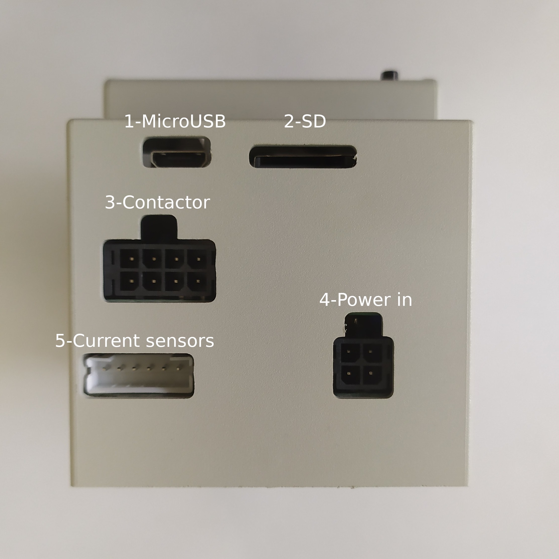
| Number | Description | Part Number |
| 1 | Micro USB host | |
| 2 | SD | |
| 3 | Contactor | Wurt Elektronik - 662008113322 |
| 4 | Power input | Wurt Elektronik - 662004113322 |
| 5 | Current sensors | JST - PHR-6 |
Bottom view
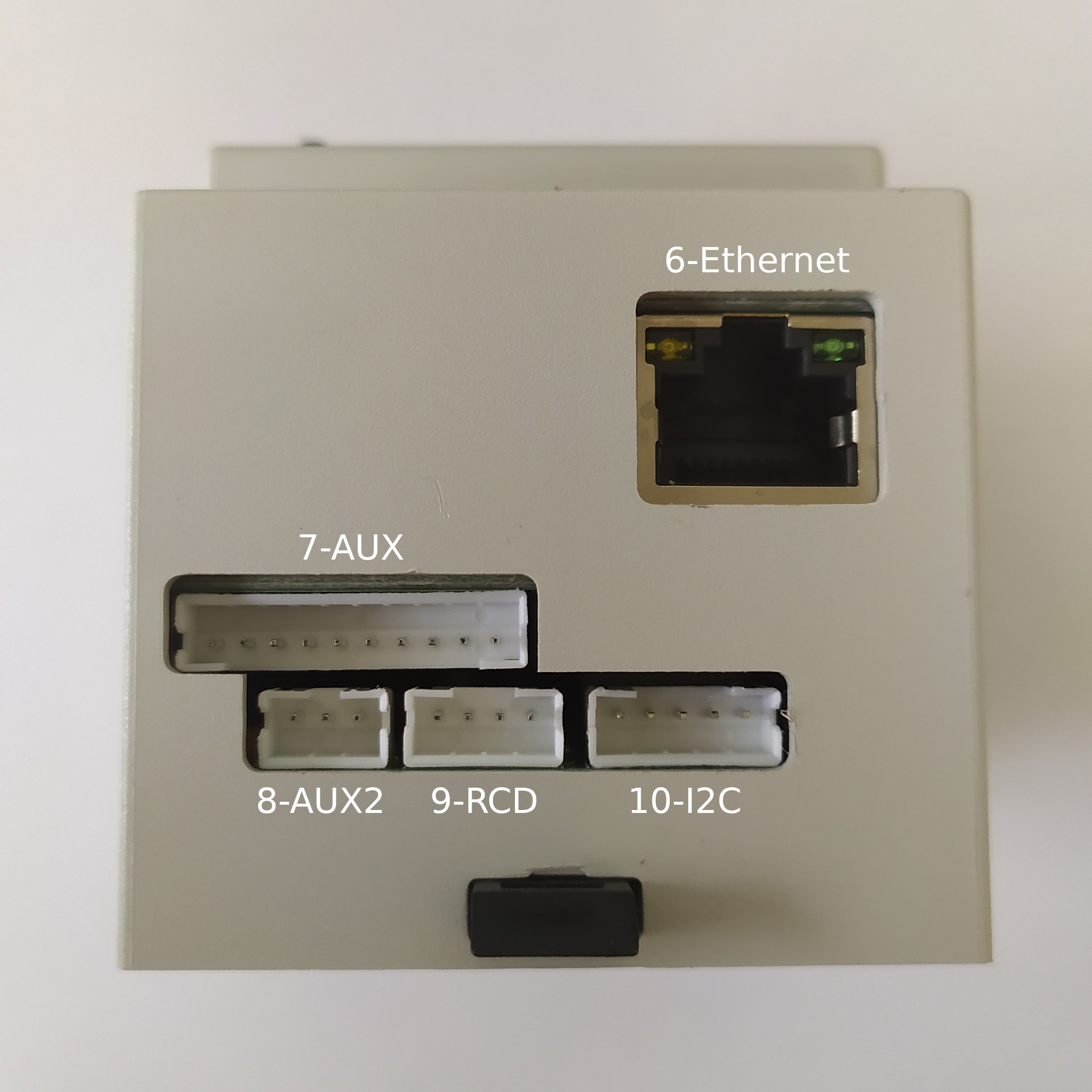
| Number | Description | Part Number |
| 6 | Ethernet | |
| 7 | AUX | JST - PHR-10 |
| 8 | AUX2 | JST - PHR-3 |
| 9 | RCD | JST - PHR-4 |
| 10 | I2C | JST - PHR-5 |
Connectors
1. Micro USB host
Warning
Max 250 mA
2. SD
Micro SD slot to expand storage
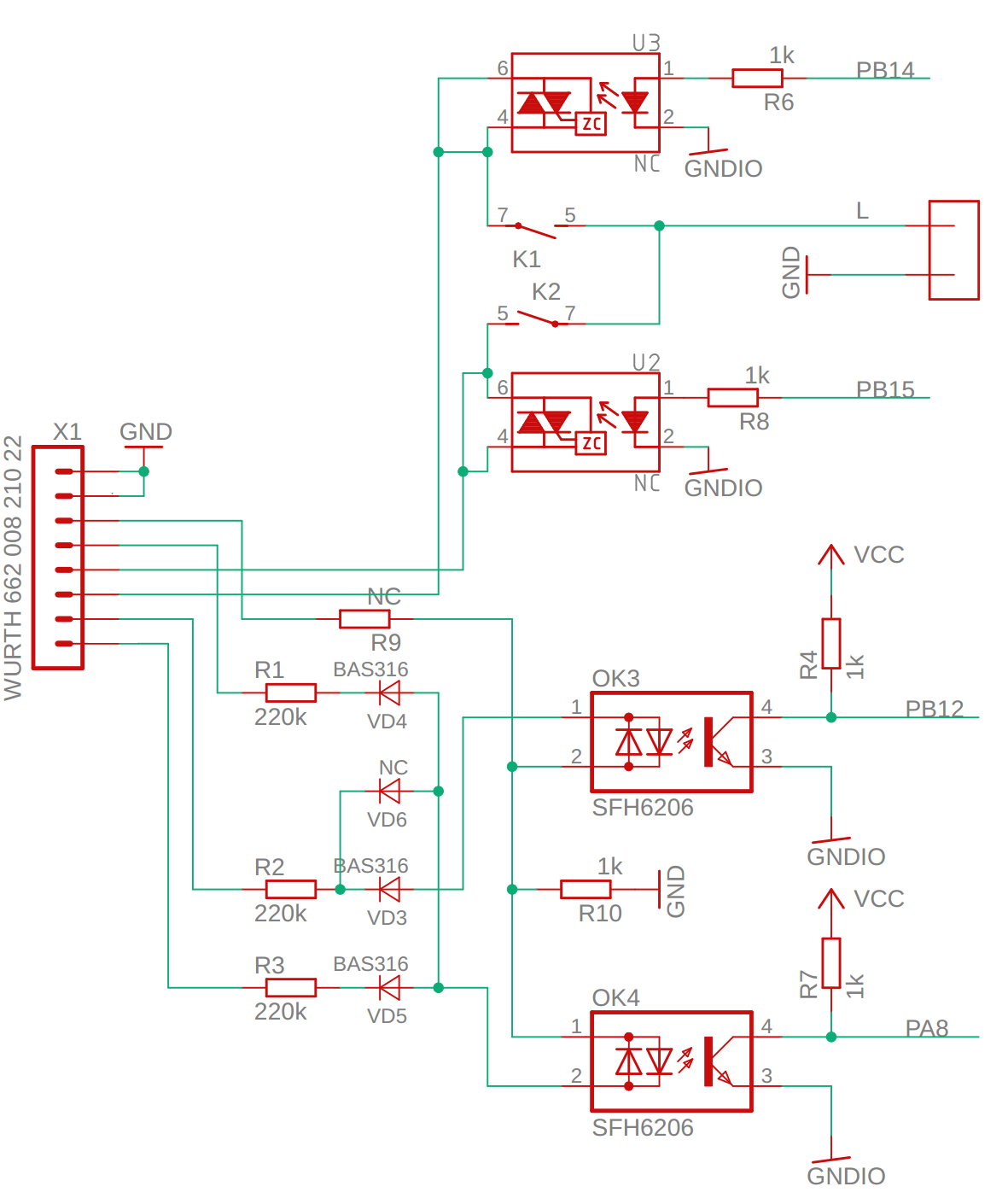
3. Contactor
Drive contactors and check stuck condition.
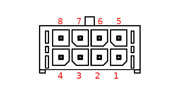
| Pin | Signal | Description |
| 1 | N | Neutral |
| 2 | N | Neutral |
| 3 | Ns | Neutral out sense (not used) |
| 4 | LAs1 | Line out sense A input 1 |
| 5 | CL2 | Contactor 2 Live terminal |
| 6 | CL1 | Contactor 1 Live terminal |
| 7 | LBs1 | Line out sense B input 1 |
| 8 | LAs2 | Line out sense A input 2 |
LAs1, LAs2 and LBs1 are connected to optocouplers to detect high voltages at the output of the contactor, to detect a welded contact.
Contactor coils can be driven by internal relays output. Connect the main one on pin 2 and 6, and the secondary one to pins 1 and 5.
Check the Connection diagram for more details
4. Power input
Connects to neutral and all phases available (1 or 3).
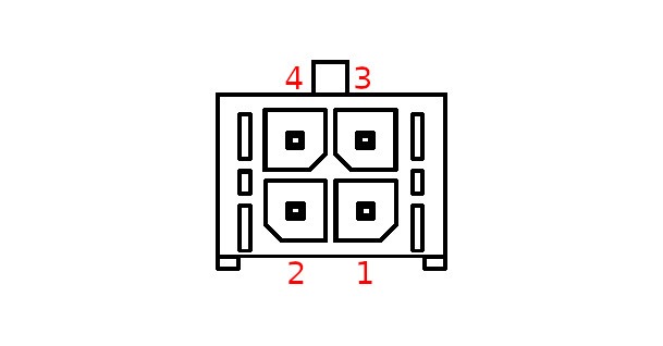
| Pin | Signal | Description |
| 1 | L3 | Phase 3 |
| 2 | L2 | Phase 2 |
| 3 | N | Neutral |
| 4 | L1 | Phase 1 |
5. Current sensors
Connects to the TA current sensor(s).
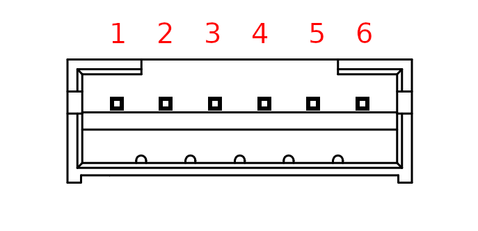
| Pin | Signal | Description |
| 1 | A_P | Phase A TA input + |
| 2 | A_N | Phase A TA input - |
| 3 | B_P | Phase B TA input + |
| 4 | B_N | Phase B TA input - |
| 5 | C_P | Phase C TA input + |
| 6 | C_N | Phase C TA input - |
6. Ethernet
7. AUX
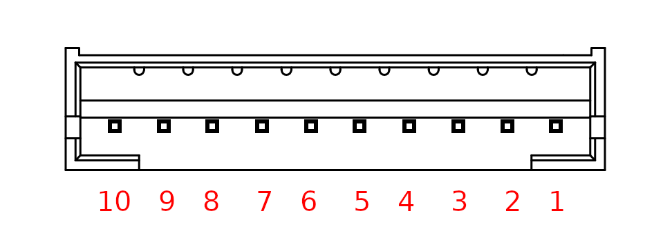
| Pin | Signal | Description |
| 1 | PO2 | Pilot signal out 2 |
| 2 | PO1 | Pilot signal out 1 |
| 3 | RSB | RS485 - |
| 4 | RSA | RS485 + |
| 5 | CANH | CAN high |
| 6 | CANL | CAN low |
| 7 | LEDOUT | Programmable digital output, internally pulled up |
| 8 | GND | Ground |
| 9 | GND | Ground |
| 10 | VCC | 5V |
8. AUX2
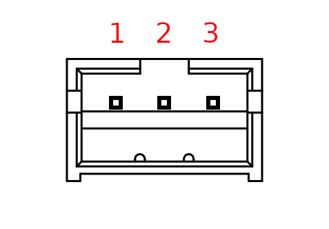
| Pin | Signal | Description |
| 1 | VCC | 5V |
| 2 | LEDOUT | Programmable digital output, internally pulled up |
| 3 | GND | Ground |
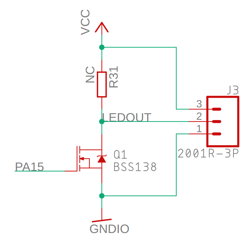
Connector internal schematic:
9. RCD
Connects to an RCM14-03 residual current monitor.

| Pin | Signal | Description |
| 1 | GND | Ground |
| 2 | +12V | 12V |
| 3 | TEST | RCD test output |
| 4 | RCD_FAULT | RCD fault input |
10. I2C
I2C bus for communications. Internal 4K7 resistors.
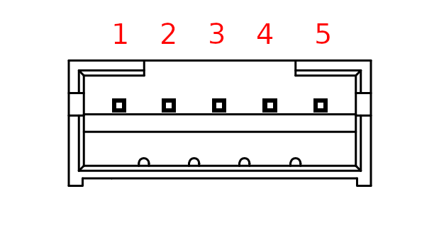
| Pin | Signal | Description |
| 1 | NC | - |
| 2 | SCL | I2C SCL |
| 3 | SDA | I2C SDA |
| 4 | 3V3 | 3.3V |
| 5 | GND | Ground |
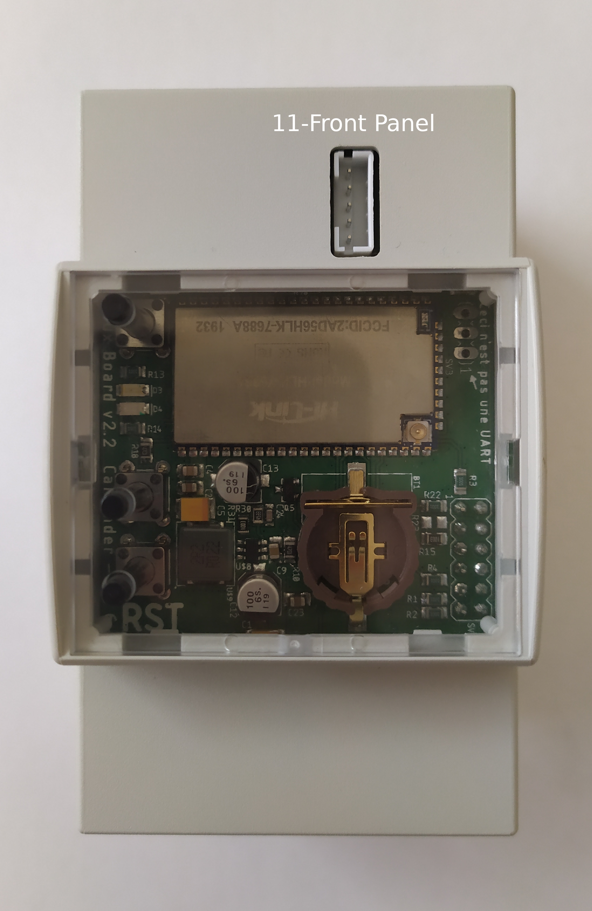
11. Front Panel
Connects to front panel.
Warning
All logic must be at 3.3V
| Pin | Signal | Description |
| 1 | RST | Reset |
| 2 | RX | Serial receive |
| 3 | TX | Serial transmit |
| 4 | 5V | 5V |
| 5 | GND | Ground |